Abstract
Background. Research is required to characterize peri-implant strain distribution associated with different restorative designs.
Objectives. This in vitro qualitative photoelastic stress analysis aimed to compare the influence of retention modality (screw-retained or cement-retained) on strain development around implants supporting different 3-unit posterior restorative designs.
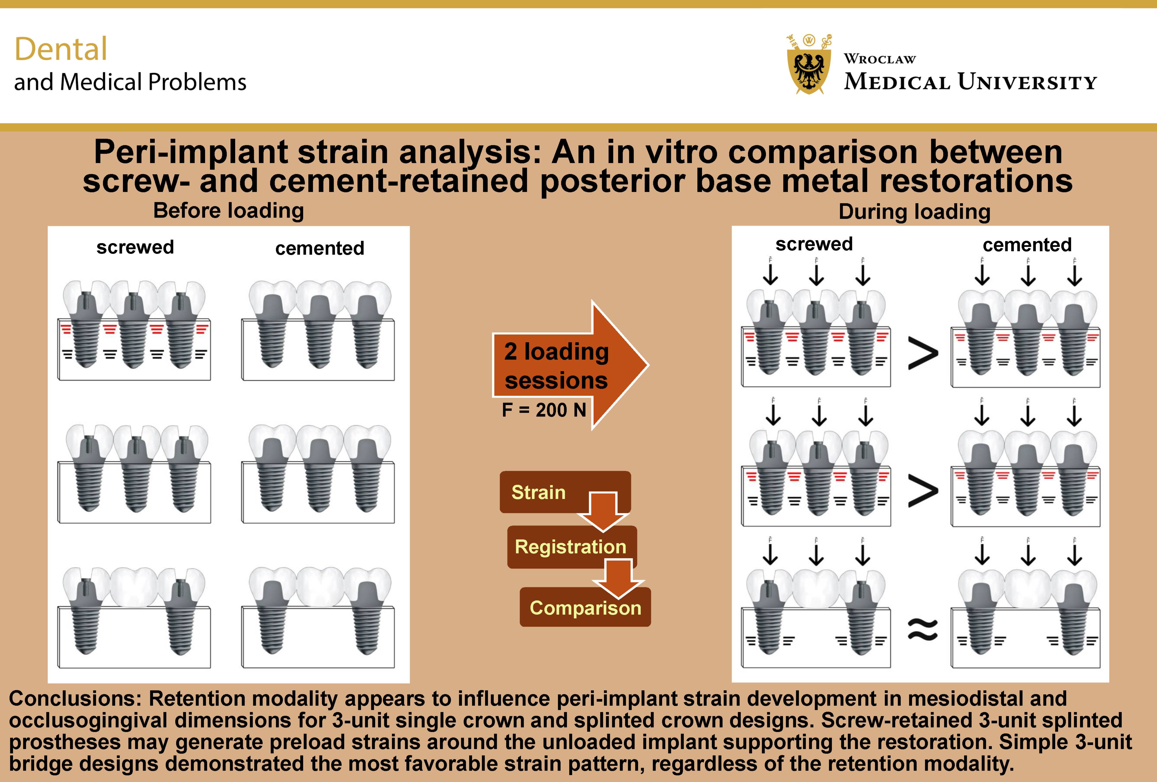
Material and methods. Six prosthetic restorative designs were evaluated according to retention modality and prosthetic configuration: 3 single crowns, cement-retained and screw-retained (SC-c and SC-s, respectively); 3 splinted crowns (SP-c and SP-s); and simple 3-unit bridges (SB-c and SB-s). All prosthetic units were morphologically identical. A photoelastic resin block incorporating 3 implants was mounted on a loading device that applied vertical loads of 200 N simultaneously at 3 identical loading points on each restoration to simulate chewing, occlusal clenching and deglutition. Fringe lines were photographically recorded and qualitatively analyzed after placement of the restorations and during loading.
Results. Screw-retained restoration with splinted crowns (SP-s) was the only design to exhibit strain in the unloaded state following placement, representing preload strain. Loading-induced strains were observed in SC-c and SC-s, with lower strain levels for SC-c than for SC-s, and in SP-c and SP-s, with lower strain levels for SP-c than for SP-s. Both configurations also exhibited crestal strains. The simple bridge (SB) designs revealed purely axial strains, with no crestal strains, regardless of retention modality.
Conclusions. Retention modality appears to influence peri-implant strain development in mesiodistal and occlusogingival dimensions for 3-unit single crown and splinted crown designs. Screw-retained 3-unit splinted prostheses may generate preload strains around the unloaded implant supporting the restoration. Simple 3-unit bridge designs demonstrated the most favorable strain pattern, regardless of the retention modality.
Keywords: preload, strain, photoelastic analysis, cement retention, screw retention
Introduction
High success and survival rates have demonstrated favorable clinical performance of posterior partial implant-supported restorations fabricated using various prosthetic materials, implant dimensions and combinations of grafting materials.1, 2, 3, 4, 5
Research continues to focus on the circumstances and etiologies of technical and biological complications associated with implant-supported restorations.6 Crestal bone loss around implants is a key feature in the definition of peri-implantitis.7 Most etiological factors are related to the presence of oral biofilm, which initiates the infectious and inflammatory processes involved in peri-implantitis and may subsequently result in bone loss.8, 9, 10 Surgical procedures involving exposure of osseous tissue may themselves induce postoperative crestal bone loss.11 Occlusal factors have also been considered to be associated with the onset and progression of crestal bone loss, both historically and in contemporary research.12, 13, 14, 15 Theoretical as well as more substantial explanations for peri-implant crestal bone loss have been proposed, linking this pathology to functional overload.15, 16 The role of occlusion in the initiation and progression of crestal bone loss therefore remains relevant, particularly in light of clinical studies associating peri-implant pathology with occlusal overload, although not exclusively.14, 17
Our research group has previously investigated the impact of occlusal loading on buccolingual strain recorded within 3-unit prostheses.18 Altering the restorative configuration was found to significantly influence strain development within the implant neck.18, 19 Changing the direction of force also had a significant mechanical effect at the same location.18 Stress is transferred through the implants and restorative components and is expressed as strain according to the different moduli of elasticity of the various elements before reaching the surrounding bone.20 The application of multiple simultaneous contacts to all restorative units represents an attempt to simulate parafunctional activity, such as static clenching, as well as routine functions, including chewing and swallowing.21, 22, 23
Apart from prosthetic design, the composition of the crown material has also been documented in vitro as a factor influencing crestal strain under load.24
One of the key components of restorative design is the retention mechanism, which is currently divided into screw retention and cement retention.25 Both are legitimate treatment approaches with proven long-term survival rates, provided that clinicians consider the known limitations associated with each retention form.26, 27 These include concerns regarding excess cement, which may contribute to peri-implant disease, and the higher probability of screw loosening and porcelain chipping associated with screw-retained prostheses.27, 28 Limited retrievability of cement-retained restorations has also been regarded as a well-known drawback. However, recent evidence suggests that newer cement-retained designs may facilitate retrieval through improved retrieval techniques.29, 30
Although screw-retained restorations have gained considerable popularity concomitantly with the increasing use of digital impression procedures,31, 32 several clinical studies and reviews have suggested a possible cause-and-effect relationship between crestal bone loss and screw retention mechanisms.33, 34 Other reports have found no influence of the retention mode on crestal bone response.35 Conversely, laboratory studies have indicated that welding techniques, framework material and mode of engagement may reduce stress development within the crestal zone.36, 37 Such clinical and in vitro evidence may reflect differences in the strain imposed on the peri-implant crestal bone. Nevertheless, to the best of our knowledge, no direct observations relating peri-implant strain to retention mechanisms have been reported.
Scientific evidence in implant dentistry should establish whether, despite its rising popularity, screw retention induces excessive peri-implant crestal strain beyond known biomechanical limits, above which pathological bone remodeling may occur.15
It is therefore important to investigate potential mechanisms and hypotheses linking the retention mechanism and prosthetic design to crestal bone loss through peri-implant strain.
Strain developing within an implant may also be transferred to the surrounding bone. Photoelastic analysis is a highly illustrative method for realistic simulation and visualization of such strain.38 The resulting peri-implant strain can be evaluated using photoelastic resin surrounding the implants and simulating bone, in which the resulting fringe patterns can be visually inspected. Such a model provides a clear representation of strain development around implants supporting a fixed restoration along the implant surface, although the analysis remains confined to the sagittal plane. Analysis of the fringe lines can reveal the theoretical biomechanical response of bone to a load applied at the level of the entire implant and even to smaller components within an implant.38, 39 Larger-scale photoelastic analyses have been employed to examine multi-unit restorations.40 Therefore, photoelasticity may demonstrate a relationship between the biomechanical state of the implants under loading or at rest, and crestal strain, expressed in the mesiodistal and coronoapical dimensions.
The purpose of this in vitro study was to use photoelastic analysis to evaluate peri-implant strain elicited by the installation and loading of various 3-unit posterior fixed prostheses and to compare the effects of the retention mechanism and prosthetic design.
Material and methods
This study employed photoelastic strain analysis and was performed in the laboratories of Vishay Precision Group Corporation (Vishay Measurements Group, Raleigh, USA). It aimed to compare 3 posterior designs of cement-retained restorations with their screw-retained counterparts under simulated occlusal loading and unloaded installation conditions. The study was designed as observational qualitative research and conducted in accordance with the Standards for Reporting Qualitative Research (SRQR).41
A photoelastic model (PLM-4B; Vishay Measurements Group) was constructed. The model had a modulus of elasticity resembling that of human bone (2.8 GPa), and dimensions of 15.8 mm × 35.4 mm × 32 mm (Cat. No. S-116H).
The fringe order characteristics of the photoelastic block were provided by the manufacturer and are presented in Table 1.
Three holes were drilled into the block according to the standard surgical drilling protocol. Three implants measuring 3.75 mm in diameter and 13 mm in length were inserted (M.I.S. Implants Technologies Ltd., Bar Lev Industrial Area, Israel).
The drilling procedure was performed using drills of consecutively increasing diameters to minimize residual stress. Stress induced in the photoelastic model was relieved by placing it on a Teflon surface for 120 min at 70°C. The model was subsequently allowed to cool inside the closed oven. Stress relief was confirmed using a circular polariscope to verify the absence of residual strain. The implants were positioned linearly, with a distance of 6 mm between adjacent implants, to facilitate fringe registration. The constructed photoelastic block and the implants embedded within it remained unchanged throughout the experiment.
Transfer copings were screwed into place and interconnected with acrylic resin (DuraLay; Reliance Dental Manufacturing Co., Alsip, USA) for stabilization and precision. The open-tray technique with a polyether-based material (Impregum; 3M ESPE, Seefeld, Germany) was employed to take impressions at the implant level, utilizing a custom-made acrylic resin tray. After insertion of the analogues, a working cast was poured. Cement-retained or screw-retained abutments were mounted onto the analogues according to the retention modality and the design of the restorations they carried, using a controlled torque of 20 Ncm. An example of such a prosthesis-free and strain-free model is presented in Figure 1.
Cast base metal fixed prostheses were fabricated using a Co–Cr–Mo alloy (Remanium GM3800; Dentaurum, Ispringen, Germany). A silicone index was employed to provide identical morphology and dimensions for all 6 configurations tested. The 6 configurations were divided into 2 groups: 3 cement-retained configurations and 3 screw-retained configurations. Cement-retained restorations comprised 3 single crowns, 3 splinted crowns and a simple bridge (SC-c, SP-c and SB-c, respectively), as did the screw-retained restorations (SC-s, SP-s and SB-s, respectively). All restorations were fabricated by a single dental laboratory.
After completion of all restorations, the abutments were affixed to the implants with the same torque of 20 Ncm, according to each configuration. Prior to each loading session, the different cement-retained restorations were retained on the abutments with temporary cement (Temp-Bond NE; Kerr Dental, Brea, USA). Screw-retained restorations were tightened onto the abutments using a torque of 35 Ncm. Abutments were selectively removed when testing SB restorations. Remaining unloaded implants in the photoelastic block did not interfere with recording the fringe order, as shown in a previous study.42
A custom-made load application device was created to apply a vertical load of 200 N to each of the 6 restorations. The load was transmitted to the restoration through loading pins, with 3 pins applying the load simultaneously. Each vertical loading session lasted 40 s, and images were captured 20 s after loading began using a digital camera. This procedure was repeated twice to verify the uniformity of the results. The photoelastic model was left to rest for 5 min between loading sessions to allow for stress relief. A white halogen light source was used with the aid of a Fresnel lens positioned between the light source and the tested assembly. Photographic recordings during the 5-min recess without loading verified the absence of residual stress in the photoelastic resin. The loading sessions then resumed.
Images were captured (Nikon D80; Nikon Corp., Tokyo, Japan) and further analyzed using image-processing software (Adobe Photoshop CS3; Adobe Inc., San Jose, USA). The images were classified according to the number of fringes and their locations in each sample using the manufacturer’s reference table (Table 1). Fringe number and fringe color indicated strain intensity. All images were evaluated by the same operator (JN).
Results
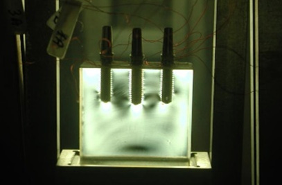
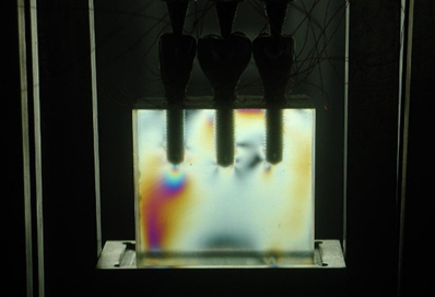
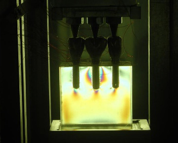
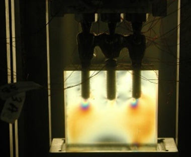
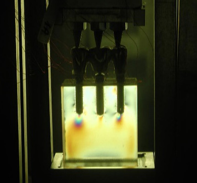
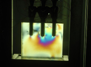
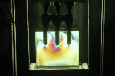
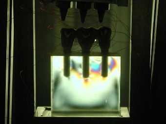
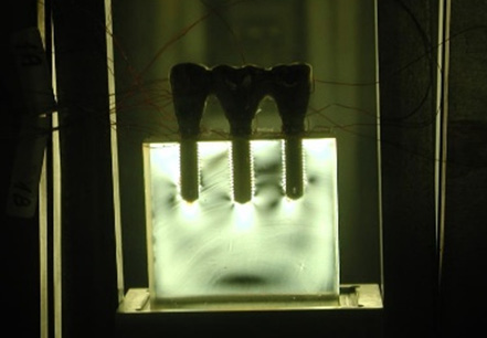
Visual representation of the strains is presented in Figure 1, Figure 2, Figure 3, Figure 4, Figure 5, Figure 6, Figure 7, Figure 8. Figure 1 shows the block’s baseline strain-free state, to be compared with the subsequent installation and loading strains. Figure 2, Figure 3, Figure 4, Figure 5, Figure 6, Figure 7 show the loading strains for the 6 configurations: Figure 2 and Figure 3 compare the loading strains of SC-s and SC-c, respectively; Figure 4 and Figure 5 compare the loading strains of SB-s and SB-c, respectively; and Figure 6 and Figure 7 compare the loading strains of SP-s and SP-c, respectively. No strains were registered during the installation of the prostheses (zero load application) except for SP-s, which demonstrated strain fringes as presented in Figure 8. Fringes were concentrated between the right and middle implants, as well as on the opposite side of the right implant, reaching the crestal bone on both sites. Such a clear representation of strain in a seemingly stress-free/load-free state demonstrates the preload status of the restorations. Figure 9 shows SP-c in its strain-free status during installation, which serves as a representation of all installation conditions with SC and SB configurations for both retention modalities.
Fringes concentrated at the implant apex alone indicate pure vertical or axial loading. Fringes on the proximal aspects reflect non-axial loading with bending strains, while fringes on the proximal and apical aspects represent combined compression and bending stresses.
The strains were divided into installation strains, defined as readings registered during the fixation of the cast restorations, and loading strains, indicating strain development during loading sessions.
By visual comparison between the 6 unloaded assemblies and the prosthesis-free model (Figure 1), mounting the screw-retained splinted prosthesis (SP-s) was the only circumstance that produced detectable strain before loading, demonstrating peri-implant preload strain.
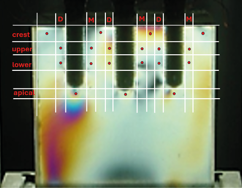
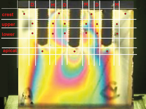
Quantification of the strain magnitude was achieved using 19 points of interest for each configuration, including 15 peri-implant locations and 4 crestal locations. An example of such an analysis is shown in Figure 10 and Figure 11. Table 2 presents the fringe values recorded during the installation of SP-s, describing its preload strain. Table 3 shows the strain magnitude induced by simultaneous vertical loading of all 6 prosthetic assemblies. Table 4 illustrates the differences in the summed fringe orders between the various configurations at 3 levels: apical; crestal; and interproximal.
When examining the loaded assemblies, several features of strain distribution were observed. Cement-retained restorations with single crowns showed off-axis strain development, particularly along both sides of the middle implant, diminishing toward the crestal zone, with apical strains indicating axial stress around all implants. Screw-retained restorations with single crowns showed no uniform strain distribution, unlike SC-c. Crestal strain was evident on the right side of the middle implant, at the top of the crest, and considerable apical strain was evident around the left implant, which exhibited the highest apical strain among all SC assemblies (Table 3). Crestal strain was higher in SC-s than in SC-c, while apical strain was higher in SC-c than in SC-s (Table 4).
Cement-retained restorations with splinted crowns manifested axial and non-axial strains around the middle implant, as observed with SC-c, but with higher intensity than in SC-c. Screw-retained restorations with single crowns revealed much higher strain intensities than SP-c, mainly around the middle and right implants. Crestal strains were also noticeable adjacent to the necks of these 2 implants. According to the sum of the strain readings, higher strains were registered in SP-s than in SP-c (Table 4).
Simple bridge assemblies showed only apical strain concentrations around all flanking implants with both retention modalities. No significant change was observed between the retention modalities (Table 4). The unloaded middle implants in SB-c and SB-s exhibited apical strains as a result of the large stress fields originating from the loaded flanking implants. These potentially misleading strains were deliberately omitted from Table 3 and Table 4. Simple bridge assemblies showed no crestal or interproximal strain with either retention modality.
Discussion
Qualitative analysis was used in the present study, as in previous photoelastic studies.43, 44, 45, 46 The assessment distinguished fringe locations as apical, interproximal (either mesial or distal) and crestal. An apical location should indicate favorable stress concentration, implying a force direction parallel to the long axis of the implant. An off-axis force direction is considered less favorable and might result in biological (peri-implant) and technical (prosthetic) complications.47
There are few comparable photoelastic reports using multiple simultaneous occlusal contacts, which represent functional activities such as swallowing, chewing and static clenching, as employed in this study. The vast majority of comparable reports have used a single loading point, as mentioned in 2 previous reviews.38, 48 Furthermore, our study employed a force of 200 N, a more representative value of human functional loading.49 Therefore, only a limited number of studies are available for comparison with the present findings. The photoelastic analysis showed no horizontal strains in the implant-supported SB configuration, compared with the remaining 2 configurations, regardless of the SB retention modality. Apart from favorable stress distribution, no crestal strains were observed in SB designs. These findings confirm those of a previous finite element analysis by Latifi et al., which attributed more favorable load distribution to configurations in which the supporting units were more widely distributed and less concentrated.50 Another computerized model study by Silveira et al. reported findings after testing virtual 3-unit screw-retained fixed implant-supported prostheses, comparing 2-unit screw-retained bridge with a 3-unit screw-retained splint. The strain table at the bone level revealed findings similar to those of the present study, demonstrating an almost symmetrical strain distribution between the 2 flanking implants in the bridge and a more irregular strain pattern with higher intensity in the screw-retained splint.51
In the study by Bittencourt et al., a simple bridge, either cement-retained or screw-retained, was tested employing the same loading protocol as in our study, but with a load of 100 N. A single mesial contact point did not influence the favorable apical strain distribution around the apices of the 2 supporting implants.52 No differences were noted with regard to the retention modality when assessing simple bridge configurations, as observed in our research.
Clinical evidence also corroborates this theory. The results of a retrospective clinical study by Ravidà et al., encompassing 145 three-unit restorations identical to the 3 restoration designs tested in our study, found that the bridge configuration represented the most favorable therapeutic approach for posterior partial edentulism.53 The results of the current in vitro study support these clinical outcomes, together with the findings of Latifi et al.,50 Silveira et al.51 and Bittencourt et al.52
The results differed with regard to single crowns and splinted crowns. Naves et al. investigated photoelastically 3 configurations of 3 cement-retained crowns under 3 simultaneous vertical occlusal contacts, using a lower load (30 N) then that applied in our study.54 Their loading protocol was simultaneous, but there was no independent stress calibration for each of the 3 loading pins, and a mesial contact point participated in load distribution. The splinted and separate configurations exhibited favorable strains adjacent to the implant apices and almost no crestal strains. The fringe distribution patterns of the cemented crowns, either with contact points, contact surfaces or splinting, were similar to those observed in our study and, as in this study, were similar regardless of the splinting effect. Pimentel et al. also examined multiple-unit cement-retained prostheses under axial loads of 100 N.46 The main difference was the use of a 5-unit interim cast superstructure framework that dispersed the load from a single middle point to all 5 units instead of the multiple point contact employed in our research. Their observations also revealed fringes concentrated around all 5 implant apices, with some extending coronally toward the crest, away from the single loading point, as expected.46 Their qualitative stress analysis indicated greater strain in the loaded screw-retained restorations than in the cement-retained restorations, consistent with the findings of our study.
Crestal strains indicate a potential cause of crestal bone resorption due to occlusal overload. Identification of such a phenomenon is important because it may help identify peri-implant sites at risk of deterioration of the osseointegration process.55
Such strain may be modified by the crown material itself, because different crown materials may produce considerably different levels of strain in the surrounding bone under the same load, as previously demonstrated by El Mahdy et al.24 Restorative design might also influence crestal strain, as reported by Tonin et al.36 The authors recorded high crestal strains using both single loading points and multiple loading points, as in our research, applied to 2 types of screw-retained restorations. Both loading protocols yielded high crestal strain due to the presence of a distal cantilever, which may serve as an example of the deleterious effects of unfavorable stress and strain.36
In the present study, installation of the screw-retained splinted restoration, before the loading sessions commenced, revealed residual strains within the photoelastic block, representing preload. This phenomenon was not observed in any other prosthetic assembly during the preload stage and has been documented in previous in vitro studies in association with unloaded screw-retained restorations. The clamping effect created within the prosthetic complex as a result of prosthetic screw tightening is believed to initiate this phenomenon.56, 57 Due to screw tightening, the crown may be minimally deflected from the implant axis and, during loading, may generate a bending moment associated with this deflection. In a splint, there is a summation of the total misfit of the component parts, and consequently, the sum of the resulting moments may increase. During loading of a screw-retained restoration, these moments may further increase, resulting in greater stresses within the implants and supporting structures.
With regard to SC restorations, we observed a similar strain pattern between SC-c and SP-c around the middle implant. This may indicate the importance of the interproximal contact point, which may produce a “splinting” effect among separate units through load distribution and arch continuity. Previous photoelastic research has emphasized the importance of contact point tightness in relation to installation strains and, through qualitative analysis, suggested a direct relationship between these 2 factors.58 Since no installation strains were detected with SC prostheses in our research, clinical examination by passing dental floss through the interproximal contact point may be considered a simple and practical method for obtaining adequately adjusted, stress-free restorations without apparent preload.
When the abutments were selectively removed according to the preplanned configuration under examination, the implants remained embedded in the photoelastic block. Under load, fringes were detected around implants in the SB configurations (Figure 4, Figure 5). These fringes were not considered relevant and were not included in the recorded measurements because they resulted from the “breakwater effect” created by the unloaded implants when positioned within the stress field of the photoelastic block.34 It is well documented that a photoelastic stress field can extend a considerable distance from the initially loaded implant, to a point where a neighboring implant may be exposed to part of the propagated strain field.39 Such a factor may be misleading when strain fringes are counted and therefore highlights the major advantage of qualitative analysis.
The limitations of this study are considerable. Masticatory forces are known to include additional significant non-axial force components,59 which may intensify the differences between the restorative designs. Although strain was evident in certain in vitro situations, this does not directly reflect true bone behavior in vivo.
Future research may focus on strain evaluation and development in the buccolingual dimension in order to construct a more accurate spatial representation of peri-implant strain. This may facilitate more appropriate planning of implant placement, contributing to better occlusal load dissipation within the bone, which may create favorable conditions for preventing peri-implant disease.20 Additionally, other forms of screw-retained restorations, such as UCLA restorations, multi-unit screw-retaining abutments or screw-retrievable crowns,23 should also be compared with cement-retained restorations.
Conclusions
Within the limitations of this in vitro study and based on its outcomes, the installation of screw-retained 3-unit splinted restorations on screw-type straight abutments resulted in mesiodistal and occlusogingival peri-implant preload strain within the surrounding medium, including the crestal region. When loading was applied simultaneously in an axial direction, 2 additional conclusions could be drawn: cement-retained restorations exhibited less peri-implant strain in 3-unit adjacent single crowns and 3-unit splinted crowns than their screw-retained counterparts; simple 3-unit bridge assemblies exhibited similar axial strain patterns around the implants, with no crestal strains, regardless of the retention modality.
Ethics approval and consent to participate
Not applicable.
Data availability
The datasets generated and/or analyzed during the current study are available from the corresponding author on reasonable request.
Consent for publication
Not applicable.
Use of AI and AI-assisted technologies
Not applicable.