Abstract
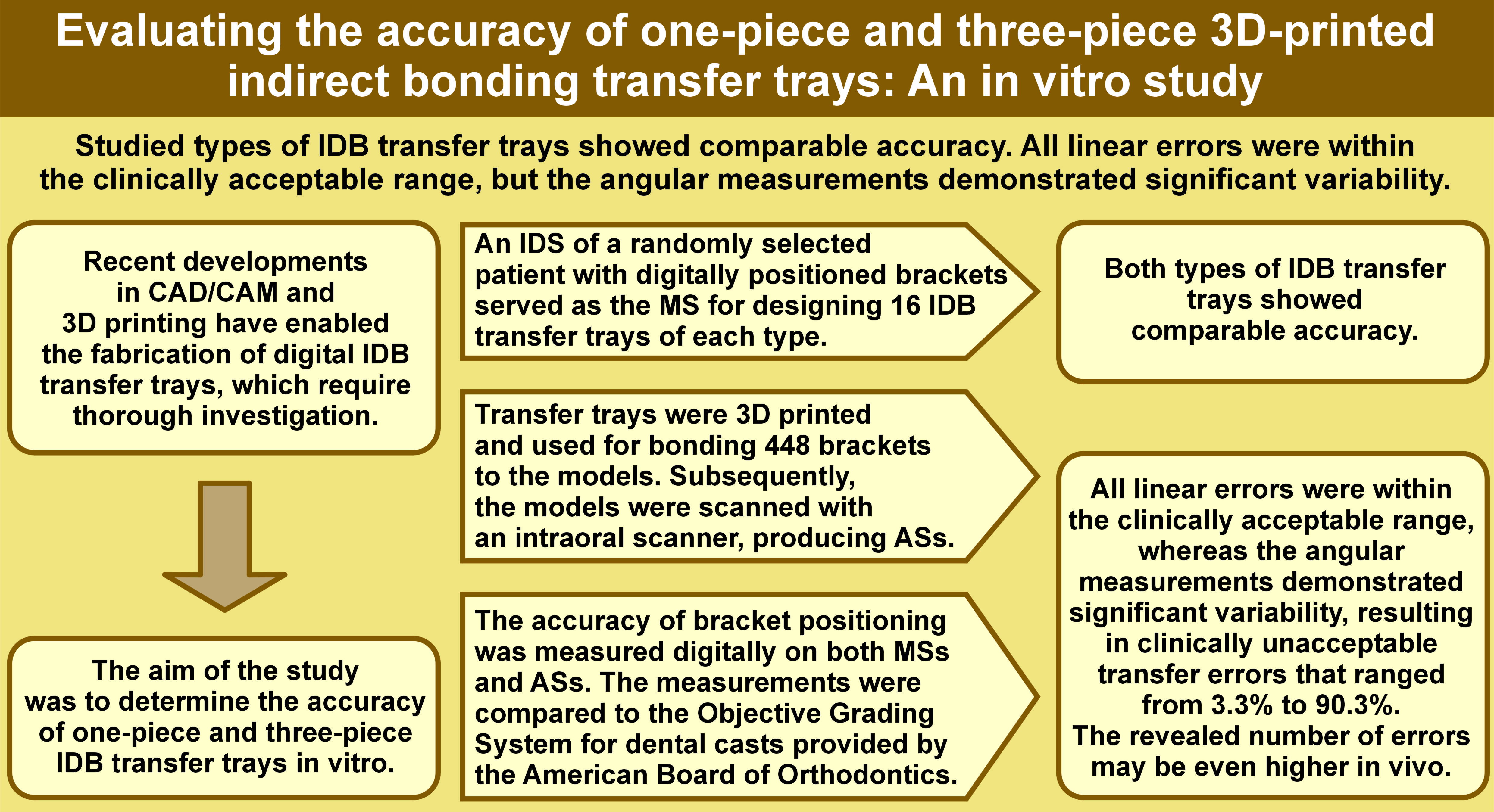
Background. Recent developments in computer-aided design/computer-aided manufacturing (CAD/CAM) and 3D printing have enabled the fabrication of digital indirect bonding (IDB) transfer trays. These modern products require thorough investigation.
Objectives. The aim of the study was to determine the accuracy of one-piece and three-piece IDB transfer trays in vitro.
Material and methods. An initial dental scan (IDS) of a randomly selected patient with digitally positioned brackets served as the master scan (MS) for designing 16 IDB transfer trays of each type. They were 3D printed and used for bonding 448 brackets to the models. Subsequently, the models were scanned with a TRIOS® 3 Intraoral Scanner (3Shape A/S, Copenhagen, Denmark), producing actual scans (ASs). The accuracy of bracket positioning was measured digitally on both MSs and ASs. The measurements were compared to the Objective Grading System for dental casts provided by the American Board of Orthodontics (ABO).
Results. The 2 types of IDB transfer trays showed comparable accuracy. All linear errors were within the clinically acceptable range, whereas the angular measurements demonstrated significant variability, resulting in clinically unacceptable transfer errors that ranged from 3.3% to 90.3%.
Conclusions. The study results cannot be unconditionally extrapolated to other types of IDB transfer trays due to the diversity of their properties and features. The study evaluated the in vitro accuracy of IDB transfer trays. The revealed number of errors may be even higher in vivo due to limitations in visibility, salivary flow, interference from the tongue, and difficulties in achieving a proper fit of the IDB transfer tray to the teeth.
Keywords: orthodontics, 3D printing, computer-aided design, orthodontic brackets, IBT resin
Introduction
Bracket positioning represents a significant challenge in orthodontic treatment with fixed appliances, the objective of which is to achieve the best results with minimal archwire bending or bracket repositioning. In this regard, the indirect bonding (IDB) technique offers considerable promise. This method, which employs transfer trays, was first proposed in 1972 by Silverman et al.1 Since that time, various modes of IDB have been developed, and numerous studies have been conducted to examine the precision of bracket positioning with IDB transfer trays.2, 3, 4, 5, 6, 7, 8, 9, 10, 11, 12, 13, 14, 15, 16, 17
Current IDB transfer trays are manufactured from a variety of materials, each with distinct properties, that are important in orthodontic treatment.3, 4, 6 Transfer trays made of thermoplastic materials are known for their ease of use and adaptability to the dental arch. However, their flexibility and susceptibility to distortion raise concerns about the precision of bracket placement.4, 6 Conversely, silicone-based transfer trays offer improved rigidity and accuracy, although their increased stiffness can sometimes complicate their application.3, 4, 6, 11, 13 Substantial advancements in computer-aided design/computer-aided manufacturing (CAD/CAM) have enabled the digital design and fabrication of IDB transfer trays using resin for 3D printing. The digitization of IDB transfer tray fabrication, particularly through resin 3D printing, represents a significant advancement in orthodontic treatment modalities. These modern, digitally-designed products offer previously unattainable customization. However, rigorous scrutiny is required to validate their reliability and efficacy. An important aspect of this advancement is the introduction of IDB materials in 3D printing. These materials, which are characterized by softness and susceptibility to damage, differ from traditional 3D-printing materials18, 19, 20 and cannot endure extended storage or undergo polishing like other materials used in dental applications.
The objective of our study was to evaluate the precision of bracket bonding using IDB transfer trays created with 3D-printed biocompatible resin. The focus of the study is on assessing the accuracy of these trays in both one-piece and three-piece designs, while also highlighting the advancements in material science and digital technology in orthodontics. This study addresses not only the technical aspects of IDB tray fabrication but also the clinical implications of these advancements, evaluating their impact on treatment outcomes and efficacy.
Material and methods
IDB transfer tray management
A randomly selected patient’s occlusion was scanned using a TRIOS® 3 Intraoral Scanner (3Shape A/S, Copenhagen, Denmark) with an accuracy of 6.9 µm, resulting in the initial dental scan (IDS). The patient presented with Angle Class I malocclusion on the right side and Angle Class II malocclusion on the left side, in addition to dental crowding, a normal overbite and an increased overjet. Subsequently, virtual pre-torqued brackets (Victory Series™ LP Roth 022 APC Flash-Free; 3M ESPE, St. Paul, USA) were placed on the virtual teeth of the IDS using Ortho Analyzer 2019 software (3Shape A/S), resulting in the master scan (MS). Based on the MS, transfer trays for the IDB were designed to rest solely on the teeth, thus avoiding contact with the gingiva and fully covering the brackets, with the exception of the undercuts of the gingival bracket wings. The thickness of each IDB transfer tray reached 2.3 mm around the brackets and at least 4 mm in the occlusal part.
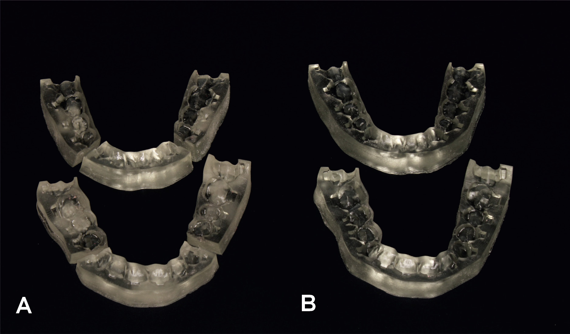
At this stage, the virtual IDB transfer trays were divided into 2 groups based on the transfer mode: Group I – one-piece IDB transfer trays (n = 16); and Group II – three-piece IDB transfer trays (n = 16). In Group II, the IDB transfer trays were designed similarly to those in Group I, but were divided in CAD software into 3 segments: an anterior segment extending from the right canine to the left canine; and 2 lateral segments extending from the first premolars to the second molars. The IDB transfer trays were subsequently 3D printed on the SprintRay Pro 95 3D printer (SprintRay Inc., Los Angeles, USA) using a transparent biocompatible resin specially designed for IDB transfer trays (NextDent Ortho IBT; Nextdent, Soesterberg, the Netherlands), with an accuracy of 50 µm (Figure 1).
The IDS was 3D printed using Model Gray resin (SprintRay Inc.) with an accuracy of 50 µm, serving as the initial model (IM), and replicated 32 times. The obtained models were coated with Transbond XT LC Adhesive Kit (3M ESPE). The material was applied to the models using compressed air and cured on each tooth with a Valo™ X polymerization lamp (Ultradent Products, Inc., South Jordan, USA) in normal mode for 20 s. Metal brackets with pre-applied adhesive were used in the study (Victory Series™ LP Roth 022 APC Flash-Free; 3M ESPE). The brackets were manually placed in the IDB transfer trays from both study groups and bonded to the models. The adhesive was polymerized with the Valo™ X polymerization lamp in Xtra Power mode, which was repeated twice for 3 s. All brackets were bonded by the same clinician.
The models with bonded brackets were scanned using the TRIOS 3 Intraoral Scanner, thereby facilitating the acquisition of the actual scans (ASs). In order to eliminate reflections on the brackets during scanning, the models with bonded brackets were coated with a thin layer of Helling 3D Scan Spray (Helling GmbH, Heidgraben, Germany) with an average particle size of 2.8 µm.
Measurements
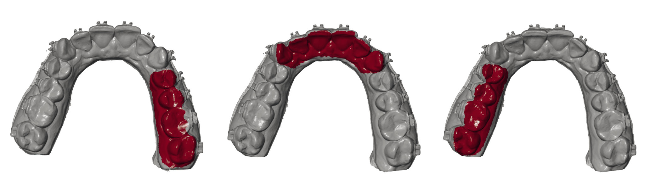
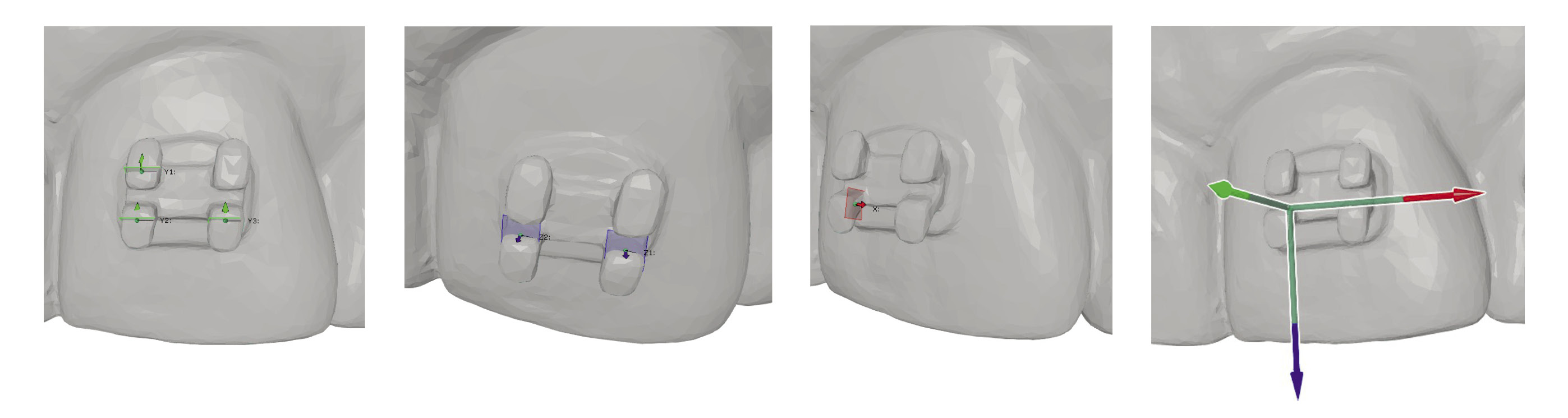
Using GOM Inspect V8 SR1 software (Carl Zeiss GOM Metrology GmbH, Braunschweig, Germany), the ASs with brackets bonded using 3D-printed IDB transfer trays were superimposed on the MSs of the patient’s dentition with brackets generated by the Ortho Analyzer software. Only the lingual and occlusal surfaces of the dentition were selected to ensure that the superimposition did not include the brackets. To prevent bias in the imposition, the dental arches were divided into 3 sections: from the right second molar to the right first premolar; from the right canine to the left canine; and from the left first premolar to the left second molar. The superimposition was conducted for each section separately in order to enable the identification of the optimal fit at the local level (Figure 2). To determine the differences between the bracket positions in the MSs and the ASs, the “3-2-1” technique was applied using the local X, Y and Z coordinate system, with the reference points illustrated in Figure 3. The 2 coordinate systems were compared using GOM Inspect software to calculate the differences between bracket positions in the MSs and the ASs and provide the linear or angular errors. The linear errors in the mesio-distal, linguo-vestibular and occluso-gingival directions were measured as the distances between the bracket positions in the MS and the AS in relation to the X-, Y- and Z-axes, respectively. Any toric, oblique, or rotational errors were measured as the inclination of the bracket positions from the MS to the AS in relation to the X-, Y- and Z-axes and noted as torque, tip and rotation, respectively. For linear measurements, a positive value indicated mesial, vestibular, or occlusal bracket displacement. For angular measurements, a positive value indicated palatal/lingual crown torque, mesial tipping, or disto-vestibular rotation of the bracket. To assess the repeatability of the “3-2-1” technique, measurements of the same model were repeated 3 times by the same experienced operator, 7 days apart.
In accordance with the American Board of Orthodontics (ABO) Objective Grading System,21 linear errors ≤0.5 mm in the proper alignment are considered clinically acceptable. This criterion was adhered to in our study, thereby enabling a reliable evaluation of the results. Additionally, given that a marginal ridge discrepancy of 0.5 mm in an average-sized molar would result in a crown tip deviation of 2°, angular errors ≤2° were also defined as clinically acceptable.
Statistical analysis
The repeatability of the measurements was assessed using Lin’s concordance correlation coefficient. Student’s t-test was performed to evaluate the bracket placement errors, and Fisher’s exact test was used to assess the prevalence of clinically acceptable transfer errors. All statistical analyses were conducted using Statistica® v. 13.3 software (TIBCO Software Inc., Palo Alto, USA).
Results
Out of a total of 448 bonded brackets, 14 were ineligible for measurements due to various reasons, including debonding during the IDB procedure or incomplete capture by the scanner. The transfer accuracy of 434 brackets was examined: 219 from Group I; and 215 from Group II, allowing for a total of 2,604 bracket positioning measurements.
Repeatability of measurements
Lin’s concordance correlation coefficient demonstrated high repeatability of the measurements, with coefficients in the order of 0.9 (α = 5%) at 0.980, 0.994, 0.998, 0.982, 0.986, and 0.997 for mesio-distal, linguo-vestibular, occluso-gingival, toric, oblique, and rotational displacements, respectively.
Errors of placement
Overall, more significant bracket displacements resulting in substantial changes in positions between the MS and the AS were observed in the mandible and in Group II (Table 1, Table 2).
Maxilla: significant results
The molar brackets in Group I demonstrated linear errors in 3 directions, resulting in more mesial, vestibular and gingival positions in the ASs compared to the MSs. The molar brackets in Group II showed significant vestibular displacement. The brackets placed on the incisors and canines in both groups were positioned more vestibularly. The brackets placed on the incisors, canines and premolars in both groups displayed additional palatal crown torque, although this torque change did not exceed 2° for the canines in Group II. The premolar brackets in Group I exhibited oblique displacement, resulting in additional distal tipping (Table 1).
Mandible: significant results
In Group I, all brackets on the incisors, canines and premolars were displaced mesially. The incisor and molar brackets in both groups, as well as the premolar brackets in Group II, exhibited vestibular displacement. The premolar brackets in Group I, as well as the molar brackets in both groups, were displaced gingivally, whereas the canine brackets from Group II were shifted toward the occlusal plane. The incisor, premolar and molar brackets in both groups, as well as the canine brackets in Group II, exhibited lingual crown torque. Mesial tipping of the incisor brackets in both groups and the premolar brackets in Group II was also observed. However, mesial rotation of the canine brackets occurred only in Group II (Table 2).
Prevalence of clinically acceptable transfer errors
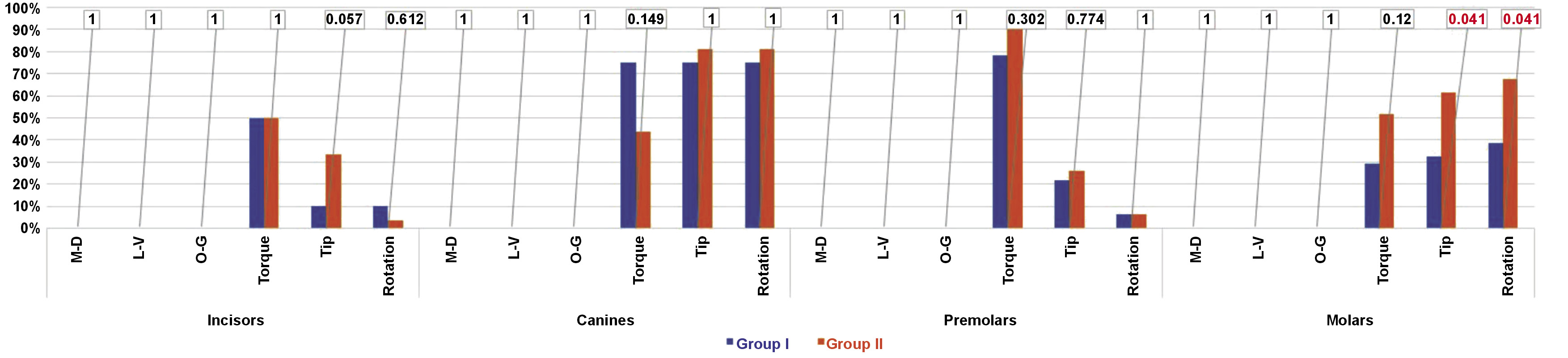
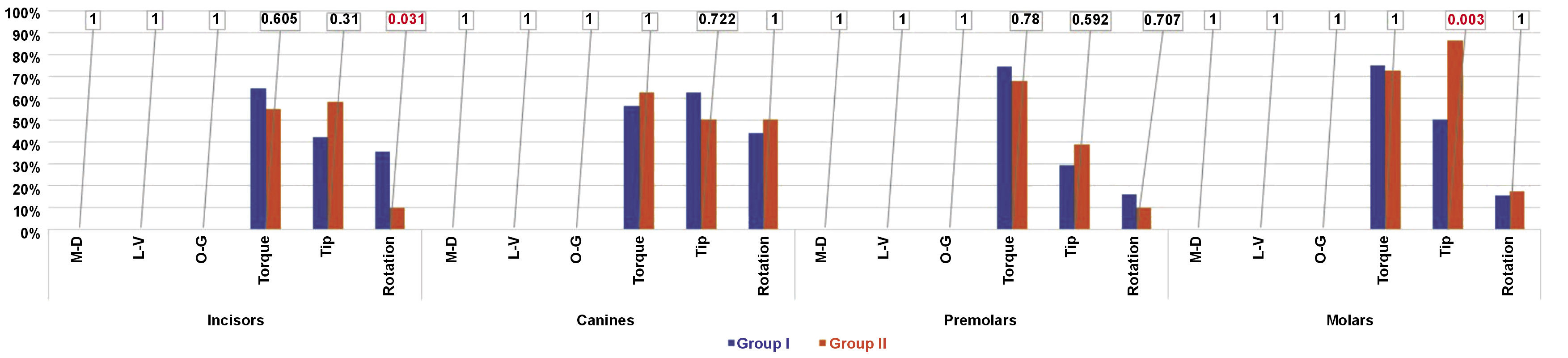
With regard to linear errors, no measurements exceeded the ABO criteria in either group. However, for angular measurements, toric, oblique and rotational errors exceeding 2° were observed in both groups, with toric errors being the most affected (Figure 4, Figure 5).
Comparison of inter-group accuracy
Regarding linear measurements, both groups demonstrated an equal accuracy of the IDB transfer trays in all dimensions, with no errors exceeding 0.5 mm (Figure 4, Figure 5).
With regard to angular measurements, the toric displacement resulting in palatal/lingual crown torque was comparable in both groups. The only significant inter-group differences were observed in molar bracket positions, with a greater number of errors in oblique and rotational angulations in Group II in the maxilla and in oblique angulation in Group II in the mandible. The mandibular incisor brackets exhibited a more pronounced rotation in Group I (Figure 4, Figure 5).
Discussion
The size of our study sample was determined based on the literature.3, 6 Out of 448 bonded brackets, we assessed 434 due to a failure rate reaching 1.7% in Group I and 2.7% in Group II, which is comparable with values found in published papers.6, 11, 16
An in vitro study by Pottier et al. evaluated the precision of hard 3D-printed IDB transfer trays compared to soft silicone transfer trays and demonstrated the reliability of the “3-2-1” measurement technique, which justifies its application in our study.11
Currently, 6 technologies are used in 3D printing: stereolithography (SLA); digital light processing (DLP); fused filament fabrication (FFF); selective laser sintering (SLS); liquid crystal display (LCD); and PolyJet. Hazeveld et al. suggested the use of DLP or PolyJet prints, as they proved to be more precise than SLA.22 However, due to the rapid evolution of 3D printing and the differences in printer designs, there is no scientific evidence to suggest that 1 method is superior in terms of providing the most accurate models. At the time of designing our study, the SprintRay Pro 95 3D printer was one of the most advanced DLP printers. To minimize bias associated with the printing process, both the models and the IDB transfer trays were printed with the highest possible accuracy of the material used, which was 50 µm.
To minimize the influence of adhesive thickness on bracket position, brackets with pre-applied adhesive were used in our study. The amount of adhesive was kept to a minimum and standardized.
A study by Zhang et al. compared 6 currently available intraoral scanners and demonstrated that the TRIOS 3 Intraoral Scanner had the highest precision (4.5 ±0.9 µm) and accuracy (6.9 ±0.9 µm), justifying its selection for our study.23 Lab scanners were excluded due to their inability to precisely capture undercuts. Nevertheless, spraying the brackets with a thin layer of scan spray was necessary to avoid reflections of the stripe light by the metal surface. The average particle size of the spray used in the present study was 2.8 µm. Although spraying the brackets by an experienced dentist significantly improved the homogeneity of the layer thickness, a resultant unquantifiable systematic error cannot be entirely excluded.24 Studies have shown that coating thickness may vary from 13.3 µm to 49.1 µm.24
The mechanical properties of the materials used for fabricating IDB transfer trays play a crucial role in ensuring the precision of bracket placement. Although these materials are easy to use and support the adaptability of IDB transfer trays, they are simultaneously prone to fragility, softness and flexibility. As highlighted by Paradowska-Stolarz et al., the mechanical properties of these materials can lead to deformation under force, resulting in deviations from the intended bracket position.18 However, studies by Schwärzler et al. demonstrate that using higher hardness materials for the fabrication of IDB transfer trays can adversely impact the effectiveness of the bonding procedure.14, 15
The 3D inspection and mesh processing software (GOM Inspect) presents data with an accuracy of up to 1 µm. In order to implement the “3-2-1” technique, 6 points were required to be marked in predefined positions. We could not rule out the possibility of inaccuracies occurring while marking the points. Therefore, we calculated Lin’s concordance correlation coefficients, which demonstrated significantly consistent repeatability of the measurements.
To ensure the accuracy of the measurements, an automatic scan overlay was used in the initial stage. It was obtained via MS and AS superimposition along the greatest number of matching areas. This method revealed discrepancies in the posterior parts of the dental arches, which demonstrated the limitations of the intraoral scanner. Despite its high resolution, the intraoral scan does not accurately represent the shape of the entire dental arch, as evidenced by Anh et al.25 Such discrepancies could also result from the model printing process itself, as demonstrated in a study by Kim et al.5 Therefore, to avoid the influence of these discrepancies on the results of our study, we sectioned the scans into 3 parts to obtain the local “best fit”.
Both types of IDB transfer trays enabled precise bracket positioning in the linear dimensions, consistent with the results of several in vitro studies.3, 5, 6, 9, 12 Although significant vestibular and gingival displacement of the brackets was observed, none exceeded the ABO criteria. However, to enhance the precision in the occluso-gingival dimension, it is recommended to apply gentle pressure in the occlusal direction on the bracket after fitting the IDB transfer tray. To ensure better accuracy in the linguo-vestibular dimension, the vestibular part of the tray should be thicker. This increases the stiffness and makes the tray less prone to deformation.
With regard to angular errors, bracket positioning was found to be less accurate and characterized by great variability, resulting in clinically unacceptable transfer errors that ranged from 3.3% to 90.3%. These results align with those reported in the literature.3, 6, 9, 13, 16, 26 Niu et al. suggested that the low accuracy of angular bracket positioning may be attributed to the design of the IDB transfer tray, specifically the filling of all undercuts in the MS, which may result in incomplete adhesion of the IDB transfer tray to the bracket surface.9 This limitation may impair the ability to control angular bracket positioning and may be considered a drawback of our study. Nevertheless, von Glasenapp et al. compared the accuracy of IDB transfer trays with jigs that fill the inner spaces of brackets, similar to those used in our study. The authors did not note the superiority of any of the evaluated IDB transfer trays in terms of angular control, indicating that filling the undercuts may not be the optimal method for preventing angular errors.12 Thicker or more rigid IDB transfer trays could enhance the angular control; however, increased thickness or rigidity may interfere with transfer tray removal and result in bond failures.
The use of CAD/CAM allows for the design and fabrication of IDB transfer trays in countless ways. However, many modalities may be affected by factors that influence the properties of trays. These factors may occur at any stage of tray manufacturing, from design through production, and they have implications for printing technology, material selection and post-processing methods. Bracket systems, which may vary in design and dimensions, may also influence the accuracy and precision of IDB transfer trays in bracket positioning.
Conclusions
In summary, it should be emphasized that our study results cannot be unconditionally extrapolated to other types of IDB transfer trays due to their diverse properties and features. Furthermore, it is important to note that our study evaluated the in vitro accuracy of the IDB transfer trays. It is possible that the error rate may be even higher in vivo due to limitations in visibility, salivary flow, interference from the tongue, and difficulties in achieving a proper fit of the IDB transfer tray to the teeth.
Ethics approval and consent to participate
Not applicable.
Data availability
The datasets generated and/or analyzed during the current study are available from the corresponding author on reasonable request.
Consent for publication
Not applicable.